Advanced MEMS Mirror Control Guide#
Introduction#
Mirrorcle’s MEMS Mirrors are gimbal-less, dual-axis, quasistatic devices with both point-to-point and resonant modes of scanning. As a result of this unique design, Mirrorcle’s devices have the fastest quasistatic beam steering capabilities in any direction.
The MEMS devices can be modeled as mechanical spring-mass systems with a high Q factor, and with bandwidth in the quasistatic regime defined by the mechanical resonance of the device. Because of this high Q factor, all of the quasistatic control schemes have a primary goal of avoiding/filtering the device’s resonant response which will ‘multiply’ the input signal and can cause overshoot and ringing that exceeds the device’s limits. The fundamental device limitation is maximum mechanical tilt that can be reached/exceeded with over-voltage and over-angle.
Note
This limit is described by the maximum mechanical tilt specified in a device’s specifications, which can be found at https://www.mirrorcletech.com/wp/support/specs/ Most importantly, the recommended maximum mechanical angle is mentioned in each device’s characterization report that is included as a PDF on the USB thumbdrive that is delivered with the devices.
Mirrorcle’s USB MEMS Controllers and Analog-/Digital-Input MEMS Drivers include lowpass filters that are designed to prevent over-angle damage from excitation of resonance. Typically, Mirrorcle recommends that the lowpass filters’ cutoff frequencies are set to \(f_{res} / 2.5\). In this simple open-loop driving configuration, the bandwidth of the device is set to and limited by the lowpass filter’s cutoff frequency. There are many more advanced ways of driving these devices to achieve higher bandwidth/frequency, and users are encouraged to explore these methods once they have become familiar with the basic operation of the devices.
Understanding the device’s response#
Often users want to validate the feasibility of different waveforms for a particular MEMS mirror design. Mirrorcle strongly recommends using the corresponding application note describing an approximate linear model for the both integrated and bonded devices:
Combined with the desired input waveform and chosen input shaping methods (discussed later), users may explore an approximation of the device’s response that accounts for its resonant frequency, Q factor, etc.
Example code#
Example code for the approximate linear model of the A7M10.2 1mm MEMS mirror is shown below in MATLAB and Python. Constants such as the resonant frequency, Q factor, and linear DC response are specific to the device, and can be found in the device’s characterization report or in the tables found in AN002 - Approximate Linear Models for MEMS Mirrors.
% Specific parameters of the device
fn = 4500;    % Resonant frequency
Q = 25;       % Q factor
k = 0.0313;   % Linear DC response [deg/V]

% Define the system's transfer function
wn = 2.*pi.*fn;               % Resonant frequency
zeta = 1./(2.*Q);             % Damping ratio
num = k*(wn^2);               % Numerator
den = [1 2.*zeta.*wn wn^2];   % Denominator
sys = tf(num,den);

% Plot the system response
figure;
step(sys);
figure;
bode(sys);
import numpy as np
import matplotlib.pyplot as plt
from scipy import signal

# Specific parameters of the device
fn = 4500       # Resonant frequency
Q = 25          # Q factor
k = 0.0313      # Linear DC response [deg/V]

# Define the system's transfer function
wn = 2*np.pi*fn
zeta = 1/(2*Q)
num = [k * (wn**2)]
den = [1, 2*zeta*wn, wn**2]
sys = signal.TransferFunction(num, den)

# Bode plot
w, mag, phase = signal.bode(sys)
plt.figure(1)
plt.subplot(211)
plt.semilogx(w, mag)    # Magnitude plot
plt.ylabel('Magnitude [dB]')
plt.xlabel('Frequency [rad/s]')
plt.subplot(212)
plt.semilogx(w, phase)  # Phase plot
plt.ylabel('Phase [deg]')
plt.xlabel('Frequency [rad/s]')
plt.show()
Open-loop control#
Overview#
The Mirrorcle Software Suite and the Mirrorcle API in general allows for quasistatic driving in open-loop with a simple low-pass filter to prevent over-angle damage from excitation of resonance. The device’s bandwidth in this configuration is set by the low-pass filter’s cutoff frequency. There are many more advanced ways of driving these devices to achieve higher bandwidth/frequency.
Mirrorcle’s application note on open-loop input shaping for MEMS Mirrors is a good starting point for users who want to experiment with input shaping methods.
Posicast Control#
Staying with the open-loop approach which is generally simpler and cheaper, there is a lot of bandwidth that can be obtained with input-shaping.
Consider the following example, which uses Mirrorcle’s A7M10.2-1000AL 1mm MEMS Mirror driven in a feedforward arrangement. To begin, the A7M10.2-1000AL’s step response is shown in the figure below. In red/blue, the unfiltered response is shown which can be seen to take ~10ms to settle at the desired angle. In green, the response is shown after the input signal is filtered with a lowpass filter with cutoff at 2200 Hz. This filtered step settles within approximately 500 us.

The step response of both axes of the A7M10.2-1000AL 1mm MEMS Mirror to an unfiltered input signal (in red/blue) and a filtered input signal (in green). Unfiltered, the step takes ~10ms to settle. Filtered, the step takes ~500 us to settle.#
The input, a step signal, is preshaped input according to the Posicast control method. For more information on Posicast, see John Y. Hung’s “Posicast Control Past and Present”
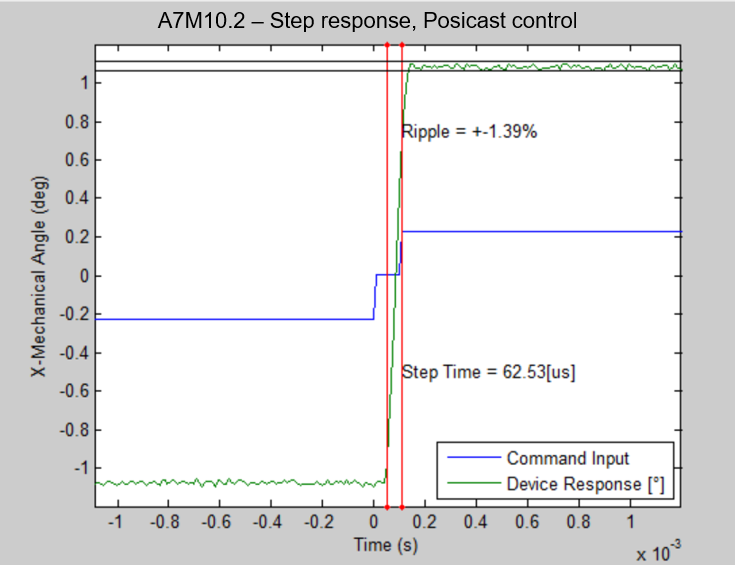
The response of an A7M10.2-1000AL 1mm MEMS Mirror (in green) plotted against the preshaped input signal (in blue). Shaping is done using the Posicast control method, and a ~62 us step time is achieved.#
A step time of ~62 us is achieved with Posicast, far exceeding the device’s bandwidth if driven with a lowpass filter at the typical cutoff frequency of \(f_{res} / 2.5 = 1800 Hz\).
Examples of other special input shaping methods with steps (Posicast and similar):
Inverse System Filter#
In the same feedforward arrangement as before, even larger increases in bandwidth utilization can be achieved when applying an inverse system filter to the MEMS drive signal. As in the case of Posicast control, the example below shows Mirrorcle’s A7M10.2-1000AL 1mm MEMS Mirror driven in open-loop with a preshaped input signal.

The response of an A7M10.2-1000AL 1mm MEMS Mirror (in green) plotted against the preshaped input signal (in blue). Shaping is done using an inverse system filter designed using an approximate linear model of the device.#
A step time of 50 us is achieved with an aggressive inverse system filter definition, which is nearly a 20% reduction in step time over the Posicast-defined input shaping method, and more than 12x faster than the device’s step time if driven with a lowpass filter at a cutoff frequency of 2200 Hz.
More on input shaping using inverse system filter method:
Other input shaping methods#
There are many other interesting and novel approaches to input shaping for open-loop control of MEMS Mirrors, see for example Prof. David Bishop’s group at Boston University:
Closed-loop control#
If the user wants to close the loop with their own PSD/optical sensor/positional feedback mechanism, there is much more bandwidth to be gained - potentially up to ~4x more. Mirrorcle’s Dev Kits do allow for experimentation with any input shaping method but do not provide closed-loop control, so users may certainly achieve wide bandwidth responses and the specifications they have in mind with a number of methods except for closed loop control.
The closed loop methodology is available to users if, for example, a position sensor is added and the Dev Kit’s USB MEMS Controller in Analog_Input_To_Output mode.
Note
Users interested in closing the loop with a position sensing device (PSD) may consider the PSD Bundle Add-on for Dev Kits provided by Mirrorcle. More information on the PSD bundle can be found here: https://www.mirrorcletech.com/wp/products/hardware/addons/
A breakdown of simple/low bandwidth driving all the way to aggressive full bandwidth driving can be found in the following publication in Sections 3, 4:
PSD-based closed loop training of an a priori known waveform, where the MEMS mirror no longer requires real-time position sensing post-training (and retains extended bandwidth/reduced non-linearity).