MEMS Mirror Programming Guide#
Initialize, Search, and Connect#
Initialize the API#
Note
This first step assumes the completion of the Quickstart guide in the Getting Started section.
Create MTIDevice instance by calling the constructor MTIDevice::MTIDevice()
MTIDevice* mti = new MTIDevice;
This handle can now be used to call any other Mirrorcle API functions
Search for Devices#
Scan for connected devices and (let user) select the target device. All detected Mirrorcle devices along with their respective
firmware and connection properties are stored in the structure MTIAvailableDevices.
To optionally print a list of Mirrorcle devices to the console, use function MTIDevice::ListAvailableDevices().
MTIAvailableDevices table;
mti->GetAvailableDevices( &table );
mti->ListAvailableDevices( &table );
To assist users in finding the right device, Mirrorcle provides ‘MirrorcleListDevices.exe’ - a tool which lists all connected Mirrorcle devices on the host.
See MTIAvailableDevices table for a full list of parameters, their corresponding enumerated code, and a brief description.
Note
If the user already knows the COM port name of the USB Controller, it is not necessary to do this step.
Connect to a Device#
Once you have searched for devices using the MTIDevice::GetAvailableDevices command, or if you already know the COM port address of the Controller, you may connect to the device using the MTIDevice::ConnectDevice command.
There are three overloads of the ConnectDevice method.
void MTIDevice::ConnectDevice( char* portName )
Opens the COM port and connects to the addressed device of format “COM#” on Windows systems and /dev/ttyUSB# in Linux.
For example: “COM23” in Windows or “/dev/ttyUSB0” in Linux
Example:
// Connect to Controller located at COM0
int portnumber = 0;
char* comPortName = new char[12];
sprintf(comPortName, "COM%d", portnumber);
mti->ConnectDevice(comPortName);
void MTIDevice::ConnectDevice( void )
Connects to the first available COM port of devices returned by MTIDevice::GetAvailableDevices() and sorted by index.
Example:
// Connect to Controller located at the first addressed device
mti->ConnectDevice();
void MTIDevice::ConnectDevice( MTISerialIO* socket )
Connects to device at a previously connected MTISerialIO socket. Typically only used internally by Mirrorcle functions.
Error Handling#
Check MTIDevice::GetLastError() method for details after transmitting data. Error codes are defined in MTIError.
Variable MTIError::MTI_SUCCESS represents successful transfer communication between API and Controller.
API waits to receive a confirmation from the Controller or times out after 2 seconds.
Example:
MTIError LastError;
LastError = mti->GetLastError();
if (LastError != MTIError::MTI_SUCCESS)
{
   // Handle the error
};
Or, alternatively:
if ( mti->GetLastError() == MTIError::MTI_SUCCESS)
{
   // Continue in the case of no error.
};
Set the Device Parameters#
After creation of the MTIDevice object, the parameter structure MTIDeviceParams is empty (values default set to 1e9).
Mirrorcle recommends to get all device parameters from the device to fill the whole structure.
Update parameters during initialization. Afterwards send the whole structure to the device.
If only a single parameter value has to be changed, it is recommended to update only the single parameter with the MTIDevice::SetDeviceParam() function.
Optionally load parameter values from a file into the MTIDeviceParams structure before sending it to the Controller using MTIDevice::LoadDeviceParams().
The parameters can also be saved into a file (including read only firmware settings).
Getting Device Parameters#
After the connection to the device is established, device parameters can be queried directly from the USB Controller. The controller responds with all of the parameters which are stored then in the MTIDeviceParams properties.
This includes read only device properties (e.g. the firmware name) and all adjustable device parameters. The first property in the class is “Success” which returns
a Boolean value showing whether the communication with the Controller was without error (Success = true) – an important property to check that validates others.
void MTIDevice::GetDeviceParams(MTIDeviceParams* params)
MTIDeviceParams params;
mti->GetDeviceParams( ¶ms );
Refer to MTIDeviceParams table for a full list of device parameters, and a brief description
Setting Device Parameters#
In most cases, user may alter some of the device parameters in the application to be different from the boot-up defaults. A single call to the SetDeviceParams function will send all values to the Controller, after the user modifies some of the parameters in the application.
void MTIDevice::SetDeviceParams( MTIDeviceParams* params )
MTIDeviceParams params;
mti->GetDeviceParams( ¶ms );
params.HardwareFilterBw = 300;
params.VdifferenceMax = 80;
params.Vbias = 70;
params.MEMSDriverEnable = true;
params.DataMode = MTIDataMode::Sample_Output;
mti->SetDeviceParams( ¶ms ); // Sends the structure to the device.
Load and Save Device Parameters#
Load parameter(s) from different files into the local structure. The structure will be (partially) updated by the provided parameters. Only writable parameters can be loaded. Please note that after loading only the local MTIDeviceParams structure is updated. The settings still need to be transferred to the device.
void MTIDevice::LoadDeviceParams( MTIDeviceParams* params, const char* fileName )
char *iniFile = "mtidevice.ini";
MTIDeviceParams iParams;
mti->LoadDeviceParams( &iParams, iniFile );
mti->SetDeviceParams( &iParams );
Save the complete MTIDeviceParams structure into a file.
void MTIDevice::SaveDeviceParams( char* fileName )
Example
mti->SaveDeviceParams( &iParams, "MyFileName.ini" );
Get and Set a Single Device Parameter#
Get a single parameter from the device or set a single parameter in the device. If a parameter during operation needs to be updated, it may be more simple or convenient to alter only that specific parameter rather than operating on the complete structure of parameters.
The two functions for individual MTIDeviceParams manipulation are:
float MTIDevice::GetDeviceParam( MTIParam param, int paramID = 0 )
void MTIDevice::SetDeviceParam( MTIParam param, float paramValue1, float paramValue2=0.f)
Example
float vMax = mti->GetDeviceParam( MTIParam::VmaxMEMSDriver );
mti->SetDeviceParam( MTIParam::VdifferenceMax, vMax * 0.75f );

// Example of SetDeviceParams with two float value inputs:
mti->SetDeviceParam( MTIParam::OutputOffsets, 0.5f, -0.155f );
Initialize Device - Example#
Initialization Example
MTIDeviceParams params;
mti->GetDeviceParams( ¶ms );
params.VdifferenceMax = 100; // Maximum Voltage in device datasheet
params.HardwareFilterBw = 300; // Recommended LPF Cutoff in device datasheet
params.MEMSDriverEnable = true;
params.DigitalOutputEnable = true;
params.SampleRate = 5000;
params.DataScale = 0.7f;
params.DeviceAxes = MTIAxes::MirrorX;
params.BootSetting = MTIBoot::Boot_With_Factory_Defaults;
mti->SetDeviceParams( ¶ms );
if ( mti->GetLastError( ) != MTIError::MTI_SUCCESS)
{
// Check for error
};
mti->ResetDevicePosition(); // Resets device position to center
Content Generation and Execution#
Output Operation#
Please note that all user-supplied coordinate data (Xdata and Ydata in normalized co-ordinates from -1 to +1 on each axis) is processed by parameters defined in the MTIDevice object.
Those parameters are applied according to the following scheme:
All User Data is stored as normalized coordinates in memory. The data is first scaled by the DataScale value (0 to 1 value). Note that data may also be rotated in this step in the x-y plane, if the rotation parameter is non-zero when setting the DataScale.
Next, the scaled data is then rotated using the MTIParam::DataRotation parameter
Then, offsets OffsetX and OffsetY are added (each can range from -1 to +1), and resulting processed values Xprocessed_data and Yprocessed_data are limited to the same -1 to +1 range.
Finally, the processed data is then converted into Biased Differential Quad channel (BDQ) outputs with Vbias and scaled with VdifferenceMax, appropriate for outputting to the 4-channel MEMS driver.
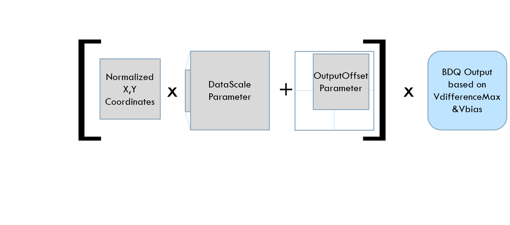
Below are the formulas describing how the normalized coordinates (in +-1 space) from the software are converted into MEMS mirror drive voltages
MTIParam::DataScale parameter
MTIParam::DataRotation parameter
MTIParam::OutputOffsets parameter
Convert to drive voltages – MTIParam::Vbias and MTIParam::VdifferenceMax
Please Note: Different output modes of operation are available and introduced on the next slides. It is possible to steer the MEMS mirror to a position by MTIDevice::GoToDevicePosition() function
or make use of different DataModes. All modes require normalized coordinates of float type for X and Y and unsigned 8-bit value, char type for M (digital output).
(X-Coordinate, Y-Coordinate, M-DigitalOutput)
Digital Output
For each MEMS position sample, there is a corresponding M Digital Output value that is outputted on the DOut connector on the MEMS controller.
These 8-bit correlated digital outputs can be used to trigger various lasers, cameras, sensors, etc.
Additionally, the DOut0 bit can be copied over to the Sync Port, which has a power and ground pin available to drive low power lasers with TTL modulation
The Digital Output port can be enabled and disabled using the MTIParam.DigitalOutputEnable.
mti->SetDeviceParam( MTIParam::DigitalOutputEnable, 0 );
Move MEMS Mirror to a Position#
The MTIDevice::GoToDevicePosition() function steers the MEMS mirror from the present position to new X, Y coordinates in a defined time in milliseconds
All necessary points inbetween are created for the mirror to move. It requires normalized coordinates (float) with an 8 bit value (unsigned char) to define the digital output state.
(X-Coordinate, Y-Coordinate, M-DigitalOutput)
void MTIDevice::GoToDevicePosition( float x, float y, unsigned char m, unsigned int mSec=5)
float xData = 0.5324f;
float yData = 0.6f;
unsigned char mData = 8;
unsigned int mSec = 10;
mti->GoToDevicePosition( xData, yData, mData, mSec );
// Go to new position:
mti->GoToDevicePosition( 0.3f, -0.44f, 128, 100 );
Note
An mSec of 0 will result in a single step being streamed where the step time is limited by the hardware filter
Note
The resulting device response is also a function of the hardware filter setting.
Send Data to the Device#
The content data has to be transferred to the device.
mti->SendDataStream( xData, yData, mData, nSamples, 0, true );
if ( mti->GetLastError( ) != MTIError::MTI_SUCCESS)
{
   // Check for error
};
If the device is already running, i.e. outputting samples, executing this command will automatically transition the device to running the new data.
The transition will occur after the transfer of data is complete and also the device completes one fully cycle of buffer output that it is already tasked to run.
If the device is not running during this command, the command will only transfer the data and the device will not automatically start executing/outputting the new data (a StartDataStream command is necessary)
Start and Stop Output Operation#
After uploading the data to the device, it will by default start outputting it immediately.
Controlled start and stop operation is also possible by calling the corresponding command. The number of repetition can be defined. For infinite runs the device will confirm the start (GetLastError) and run till it received a stop command.
It is recommended to StopDataStream before making any changes to DataMode or SyncMode params.
After the params have been changed, download content to the controller with MTIDevice::SendDataStream() and issue a MTIDevice::StartDataStream() when ready.
void MTIDevice::StartDataStream( int repeatCount = -1, bool confirmOnComplete = true )
void MTIDevice::StopDataStream()
mti->StartDataStream(  );           // Start and infinite repeat
mti->StartDataStream( -1 );         // Start and infinite repeat
mti->StartDataStream( 1 );          // Start once
mti->StartDataStream( 32 );         // Repeat 32 times (maximum)
mti->StopDataStream( );             // Stop the output operation

if ( mti->GetLastError( ) != MTIError::MTI_SUCCESS)
{
   // Check for error
};
DataModes for Input/Output Operation#
Another possibility to drive the output and to read analog inputs are DataModes.
Note
The typical maximum length is limited to 25,000 points and normalized coordinates (float) with an 8 bit value (char) to define the digital output state is required.
(X-Coordinate, Y-Coordinate, M-DigitalOutput)
These modes require different input data to be set with proper parameters before sending data. (Refer to MTIDataMode table for details)
void MTIDevice::SetDeviceParam( MTIParam param, float paramValue1, float paramValue2=0.f )
The content data (if applicable) has to be transferred. Operation can be started and stopped.
Sample_Output DataMode#
Mode Sample_Output is the default mode if no DataMode is set during initialization. The sample length is defined by the user.
First set the MTIDataMode (optional), second set the sample length, and finally send the data stream. By default output operation starts after data transfer.
void MTIDevice::SetDeviceParam( MTIParam param, float paramValue1, float paramValue2=0.f )
Example:
mti->SetDeviceParam(MTIParam::DataMode,  MTIDataMode::Sample_Output);
unsigned int nSampleLength = 5500;
mti->SendDataStream( xData, yData, mData, nSampleLength, 0, true );

// A single run start data stream can be issued
mti->StartDataStream( 1 );       //  Start and run once

// Alternatively, an infinite run start data stream can be issued
mti->StartDataStream( -1 );     //  Start and run infinitely
Sample_And_Analog_Input_Buffer MTIDataMode#
Mode Sample_And_Analog_Input_Buffer is similar to basic “Sample_Output” mode in the sense that the Controller streams X,Y,M samples to its outputs according to user-provided parameters. However in this mode, the Controller is also simultaneously storing measurements on two analog inputs into the buffer for later upload by user. As each sample is executed at the SampleRate, two analog input values are stored into the buffer.
In this mode, MTIDevice::StartDataStream() has to be used with a single repeat (cannot be set to infinity).
In this mode, the available buffer size is 1/2 of total, allotting space for storing of AI values.
To use, first stop the data stream, set the DataMode, send the data, then start operation.
Afterwards the data has to be requested from the device with GetAnalogInputBuffer.
void MTIDevice::GetAnalogInputBuffer( float* AI0, float* AI1, unsigned int DataLength )
// First stop the data stream
mti->StopDataStream();
// Set the DataMode
mti->SetDeviceParam( MTIParam::DataMode, MTIDataMode::Sample_And_Analog_Input_Buffer );
unsigned int nSampleLength = 2500;
 // Send the data to the Controller
mti->SendDataStream( xData, yData, mData, nSampleLength, 0, true );
// Start the data stream (argument of 1 scans the waveform once)
mti->StartDataStream( 1 );
float* ChannelData0 = new float[nSampleLength];
float* ChannelData1 = new float[nSampleLength];
mti->GetAnalogInputBuffer( ChannelData0, ChannelData1, nSampleLength );
Analog_Input_To_Output MTIDataMode#
MTIDataMode::Analog_Input_To_Output lets the device sample the analog inputs at maximum speed and use these values as normalized coordinates to drive the output.
When changing between any DataModes, it is recommended to first issue a StopDataStream, make the changes to the parameters, download new content, and issue a StartDataStream to begin.
void MTIDevice::SetDeviceParam( MTIParam param, float paramValue1, float paramValue2=0.f )
mti->StopDataStream();
// Stop Data Stream BEFORE changing Data Modes
mti->SetDeviceParam( MTIParam::DataMode, MTIDataMode::Analog_Input_To_Output );
mti->StartDataStream();
Analog_Input_Stream MTIDataMode#
Gets the sampled values from channel 1 or 2 as stream in real time. Gets as many as are available, returns how many were obtained.
unsigned int MTIDevice::GetAnalogInputStream( float* AI0, float* AI1, unsigned int DataLength=0 )
unsigned int npts = 800, length = 0;
float *ai0 = new float[npts], *indices = new float[npts];
length = mti->GetAnalogInputStream( ai0, indices, npts );
Real-Time Content Manipulation#
During execution the output can be modified by changing the parameters. Certain parameters can be changed in Real Time without having to download new content.
void MTIDevice::SetDeviceParam( MTIParam param, float paramValue1, float paramValue2=0.f)
Scale and/or Rotate output amplitude by changing the parameter DataScale and DataRotation.
mti->SetDeviceParam( MTIParam::DataScale, 0.5 );
mti->SetDeviceParam( MTIParam::DataScale, 0.5, 0.45 );
Change devices axes (flip and mirror) by modifying the parameter MTIAxes.
mti->SetDeviceParam( MTIParam::MTIAxes, MTIAxes::MirrorX_MirrorY );
mti->SetDeviceParam( MTIParam::MTIAxes, MTIAxes::MirrorX_FlipXY );
Apply an offset on the outputs with the parameter OutputOffsets.
X and Y offset values must be provided simultaneously, therefore two float parameters must be passed to the function.
SetDeviceParam( MTIParam::OutputOffsets, 0.1f, 0.5f );
Sample Analog Inputs#
The USB controller has 2 Analog Input channels.
Both ADC have a resolution of 12 Bit and can sample external analog signals in a range of +/- 10V.
To get one sample during operation:
float GetAnalogInputValue(unsigned int ChannelNumber)()
unsigned int ChannelNo = 1;
float OneAnalogSample = mti->GetAnalogInputValue( ChannelNo );
To sample for a defined length into the buffer:
void MTIDevice::GetAnalogInputBuffer( float* DataAI0, float* DataAI1, unsigned int DataLength )
For more information on the GetAnalogInputBuffer function, please refer to the Sample_And_Analog_Input MTIDataMode section.
Triggering and Synchronization#
Mirrorcle’s USB MEMS Controllers have two output connectors commonly used for triggering and synchronization: the Synchronization (Sync) port and the Digital Output (DOut) port.
The User Guide and pinouts for these ports can be found in the USB-SL MZ MEMS Controller User Guide.
The SyncMode parameter allows the user to set the Synchronization port on the Controller to provide triggers to external sources such as lasers, cameras, etc.
Alternatively, the Sync port can be used synchronize multiple MEMS controllers. This function re-defines the operation of the middle pin of the Sync port.
When changing between any SyncModes, it is recommended to first issue a StopDataStream, make the changes to the parameters, download new content, and issue a StartDataStream to begin.
Ensure you change the SyncMode back to MTISync::Output_DOut0 before disconnecting from the controller at the end of the session.
Synchronization (Sync) Port for Sending Triggers to an External System#
Imaging systems often require a trigger to be sent by the scanning system to indicate when an image should be captured or a timer should be started.
For systems requiring knowledge on when a scan has begun, or is being repeated, the MTISync::Output_Start_Trigger state is used. This outputs a high signal at the first sample of a data stream.
For systems requiring a clock signal to indicate when a sample has been output by the Controller to the MEMS, the MTISync::Output_Sample_Clock state is used.
void MTIDevice::SetDeviceParam( MTIParam param, float paramValue1, float paramValue2=0.f)
mti->StopDataStream();
// This sets the controller to output its current sample clock signal to the Sync port.
mti->SetDeviceParam(MTIParam::SyncMode, MTISync::Output_Sample_Clock);
mti->SendDataStream(x, y, m, numSamples);
mti->StartDataStream();
Digital Output (DOut) Port for Sending Triggers to an External System#
As mentioned in the section on Output Operation, the Digital Output number can be used to trigger external systems and/or communicate information about the scan pattern.
The digital output number is an 8-bit number that accompanies every MEMS position sample, in the format X, Y, M. This 8-bit number is sampled to the Digital Output port at the same time that the MEMS drive signal corresponding that that sample is sent by the Controller to the MEMS. This allows for more complex triggering systems when compared to the single-bit Sync port.
In standard operation, when MTIParam::SyncMode is set the MTISync::Output_DOut0, the least significant bit (0th bit) of the Digital Output number is forwarded to the middle pin of the Sync port.
This is done to govern the TTL modulation of the laser provided in a Standard Dev Kit. In practice, this results in the laser being off for even M values and on for odd M values,
most typically represented by M = 255 for laser-on sample and M = 0 for a laser-off sample
The digital output number is used more extensively by the MTIDataGenerator function, MTIDataGenerator::LinearRasterPattern(). LinearRasterPattern is used in MirrorcleDraw’s “Scan Patterns” function,
in MirrorcleLinearRaster, and in the C++ SDK’s Linear Raster generation examples as the primary scan pattern generation function.
LinearRasterPattern constructs the M values according to the following scheme:
Bit |
Described Feature |
|---|---|
0 |
Active line |
1 |
Pixels on line |
2 |
Start of the frame |
3 |
Y-axis direction |
LinearRasterPattern is only one example of how the digital output number (M) can be used to communicate information about a scan pattern to external systems. Users preparing their own scan patterns or re-interpreting Mirrorcle-generated scan patterns have full control of the output to the Digital Output (DOut) port.
Synchronization (Sync) Port for Receiving Triggers from an External System#
The MTIParam::SyncMode parameter allows the user to set the Controller’s output operation to be triggered from external sources via the Sync port.
Setting the SyncMode parameter will re-define the operation of the middle pin of the Sync port.
MTISync::External_Sample_Clock
Input an external clock signal from the Sync connector
MTISync::External_Start_Trigger
Input a start trigger signal from the Sync connector. Upon detecting the trigger signal, the device’s behavior is equivalent to
MTIDevice::StartDataStream(-1).
MTISync::External_Frame_Trigger
Input an external trigger signal at Sync connector to start single scan of a frame. Upon detecting the trigger signal, the device’s behavior is equivalent to
MTIDevice::StartDataStream(1).
void MTIDevice::SetDeviceParam( MTIParam param, float paramValue1, float paramValue2=0.f)
mti->StopDataStream();
mti->SetDeviceParam (MTIParam::SyncMode, MTISync::External_Sample_Clock);
// This sets the controller to input a sample clock signal from an external source, and run at that clock rate
mti->SendDataStream(x, y, m, numSamples);
mti->StartDataStream();
Ensure to change the SyncMode back to Output_DOut0 before disconnecting from the controller at the end of the session.
Synchronization (Sync) Port for Synchronizing Multiple MEMS Controllers#
Work with multiple MEMS Controllers with the MTISyncMode parameter and MTISync options.
In order to synchronize multiple MEMS Controllers, one Controller should be defined as the “Master” by setting its MTISyncMode setting to MTISync::Output_Start_Trigger or MTISync::Output_Sample_Clock.
All other MEMS Controllers should be “Slave” devices, with the MTISyncMode param set as MTISync::External_Start_Trigger or MTISync::External_Sample_Clock.
void MTIDevice::SetDeviceParam( MTIParam param, float paramValue1, float paramValue2=0.f)
Example (for the Master Device):
mti->SetDeviceParam (MTIParam::SyncMode, MTISync::Output_Start_Trigger);
// This sets the controller to output a start trigger at the beginning of each frame
Example (for the Slave Device):
mti->SetDeviceParam (MTIParam::SyncMode, MTISync::External_Start_Trigger);
// This sets the controller to receive an external start trigger from the Master device
Refer to the ‘Additional Parameter Tables’ at the beginning of this guide for details.
Saving Parameters and Data to the Controller#
Save to Flash – Parameters#
Store customized parameters and data in the device.
Make use of the auto run mode.
Manipulate device parameters and/or prepare output data for the device.
void MTIDevice::SaveToFlash( MTIFlash flashsave )
Example:
mti->SaveToFlash( MTIFlash::Device_Params );
mti->SetDeviceParam( MTIParam::BootSetting, MTIBoot::Boot_With_Flash_Data_And_Autorun);
To return to boot with factory defaults:
mti->SetDeviceParam( MTIParam::BootSetting, MTIBoot::Boot_With_Factory_Defaults);
Refer to the ‘Additional Parameter Tables and Settings’ at the beginning of this guide for details.
Save to Flash – Data in Buffer#
Store customized parameters and data in the device. Make use of the auto run mode. Manipulate the device parameters and/or prepare output data for the device.
void MTIDevice::SaveToFlash( MTIFlash flashsave )
mti->SendDataStream( x, y, m, npts, 0, false );
mti->SaveToFlash( MTIFlash::Data_In_Buffer );
mti->SaveToFlash( MTIFlash::Device_Params);
mti->SetDeviceParam( MTIParam::BootSetting, MTIBoot::Boot_With_Flash_Data_And_Autorun);
Refer to the ‘Additional Parameter Tables and Settings’ at the beginning of this guide for details.
Debug, Disable, and Disconnect#
Debug - Mirror Position#
Query X, Y, or M data of the sample on which the execution was last stopped.
Note
Data is only valid after StopDataStream() is executed.
Data can be used to determine where the device is relatively pointing:
Query the memory address after stop of output operation or stop command send:
Reset Mirror position to center:
Debug - Communication#
To check if the device is running (outputting data).
Clear the input buffer if the data wasn’t transferred successfully or the output is wrong.
Reset the device communication and clear receive buffer.
To reset the device to its boot-up settings:
Debug - Lost Connection#
It could happen that the user unplugs the USB connection or leaves the devices wireless range.
In case of a lost connection, it is useful to try to reconnect for a certain defined time.
The devices default timeout will be after 2 seconds.
In some cases the device will continue execution of the content before disconnection. If the output projection is affected it may be helpful to reset the mirror position after reconnection.
To verify that a device is responding to serial commands:
bool status = mti->IsDeviceResponding();
To verify that a device socket is non-NULL (should be true when serial socket is connected):
bool status = mti->IsDeviceConnected();
if (status == true)
   printf("Connected");
Disable & Save Device Parameters#
The application has to consider different events. The typical case will be the user likes to switch off the device and/or close the application.
In any case Mirrorcle recommends to disable the digital outputs and switch off the MEMS driver.
mti->SetDeviceParam( MTIParam::DigitalOutputEnable, 0 );
mti->SetDeviceParam( MTIParam::MEMSDriverEnable, 0 );
Optionally save all parameters in a file.
MTIDeviceParams sParams;
mti->GetDeviceParams( &sParams );
mti->SaveDeviceParams( "MyFileName.ini");
Disconnect & Delete Application#
Disconnect the device (this releases the COM port).
Example:
mti->DisconnectDevice();
Delete the MTIDevice object in memory:
DeleteDevice();